Walls have many functions. They give a feeling of security in that they provide privacy and protection from noise as well as providing support for slopes or raised flower beds. These functions are integrated in the good design and fascinating aesthetics of walls built with BelMuro.
The diagonal fluting creates a varied interplay of light and shadow, making the surface look different from every angle. This combines perfectly with the new Ciara paving design, the surface of which is also fluted. CleanTop surfaces are expressive, colourfast, less susceptible to soiling and easy to clean.


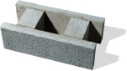


50 x 16 x 25,2 cm
With ground surface:
Depth 24,6 cm

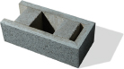
25 x 16 x 25,2 cm
With ground surface:
Depth 24,6 cm
50 x 16 x 25,2 cm
With ground surface:
Depth 24,6 cm

25 x 16 x 25,2 cm
With ground surface:
Depth 24,6 cm
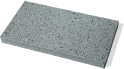
80 x 33 x 4,2 cm
With ground surface:
80 x 33 x 3,9 cm
With textured surface:
50 x 33 x 5 cm
25,2 x 16 x 25,2 cm
Bei geschliffener Oberfläche:
24,6 x 16 x 24,6 cm
33 x 5 x 33 cm
Bei geschliffener Oberfläche:
33 x 3,9 x 33 cm
Abdeckstein 4-seitig bearbeitet


, City house place, BelMuro grassano.")
,City hall place, BelMuro Grassano.")
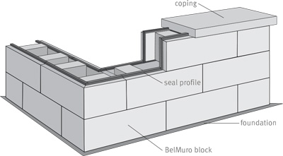
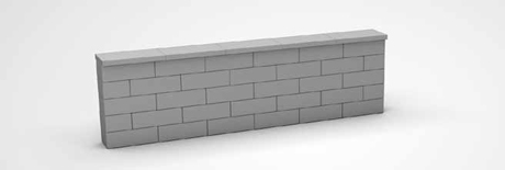
BelMuro is a wall system designed to bridge embankments. Moreover, BelMuro can be used as a freestanding wall system.
The BelMuro blocks are factory-produced cuboid concrete elements featuring two chambers arranged in a row.
They are placed with a mortar joint on a foundation which is created on-site. The blocks are laid on one another lengthwise. To secure the blocks to one another and to compensate for minor dimensional tolerances, construction glue is used to join the bonding surfaces. The resulting shadow gaps are sealed with the seal profiles which are supplied together with the blocks. For this purpose, the seal profiles are laid flush with the inside surface immediately after setting each block and angled into place to fit them to the notch in the vertical joint. Expansion joints must be installed at intervals of 5 to 8 metres, in order to prevent crack formation due to temperature expansions and to the swelling and shrinkage of the material. These expansion joints can be made by leaving a chamber created between two adjacent blocks unreinforced and filling it instead with coarse stone chippings or gravel (grain size 8-16 mm).
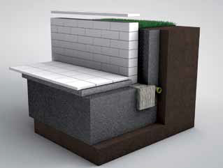
The wall system can, depending on its purpose, be constructed in two different ways. When BelMuro is used as a retaining wall to reinforce an embankment, either the chambers can be filled with concrete and reinforced or geogrids can be used in combination with a crushed stone filling. In the case of a freestanding wall, the only possible option is to fill with concrete and reinforce accordingly.
1) Freestanding and retaining walls with reinforcement up to approx. 1.00 m
(6 courses + coping):
From the foundation, two Ø 10 mm BST IV S reinforcement bars extend into the BelMuro chambers in the 25.3-cm grid. The reinforcement bars should be anchored at least 40 cm into the foundation and, depending on the total height of the wall, should extend up to 1.00 m from the foundation. The BelMuro wall is laid up to the height of the reinforcement bars. Prior to pouring, a wire reinforcement mesh (R188) is installed in the chambers. Then the wall is filled up to approx. 2 cm below the upper edge.
2) Freestanding and retaining walls from approx. 1.00 m with reinforcement
(7 courses or more + coping):
From the foundation, two Ø 10 mm BST IV S reinforcement bars extend into the BelMuro chambers in the 25.3-cm grid. The reinforcement bars should be anchored at least 40 cm into the foundation and extend up to 1.00 m from the foundation. The BelMuro wall is laid up to the height of the reinforcement bars. Then a wire reinforcement mesh (R188) is installed in the chambers. Subsequently the wall is filled to approx. 10 cm with concrete (C16/20). The second reinforcement bars (length according to the total height of the wall, up to 2.00 m) are then set into the wire reinforcement mesh and, if necessary, fixed to the frame.
The reinforcement bars overlap here by approx. 90 cm and, depending on the total height of the wall, extend up to 1.00 m from the top of the wall. Then the wall is filled up to a height of approx. 1.00 m. After the infill concrete sets, the further block courses (including seal profile) are laid, additional wire reinforcement meshes are set into the chambers, and the chambers are filled with concrete (CC16/20) up to approx. 2 cm below the top edge. Lining the chambers with concrete serves to bond the individual blocks to one another.
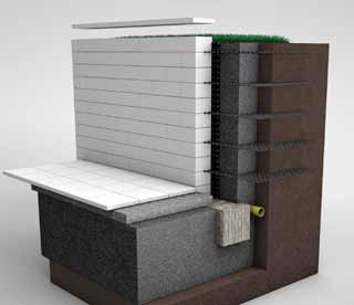
3) RETAINING WALLS from approx. 1.00 m with geogrid
(7 or more courses + coping):
For walls built to a height of 1.00 m or more, we recommend either reinforcing the wall (see above) or anchoring it into the embankment. Where no load and no pressing water is present and where the backfill soil has a kf of approx. 10-3 and an angle of repose > 32°, walls of up to 2.00 m in height can be anchored into the embankment by installing a geogrid (e.g. HUESKER Fortrac 55/30-20T). The retaining wall construction is built in sections, layer-by-layer. The blocks are laid in parallel with the placement of the geogrid, with the distribution, levelling, and compaction of the backfill material, and the filling of the blocks. The fill soil must be firmly compacted using suitable compaction equipment.
The geogrids are installed (without folds) between every third course on the front edge of the hollow chambers (cavities) to a depth of 1.75 m and stretched out smooth before the fill material is introduced. Care must be taken to ensure that the main tensile strength direction (roll direction) runs perpendicular to the wall. In order to protect the geogrids from damage and to keep them from sliding, they are covered with fill soil immediately after they are laid. The geogrids must cover the respective reinforcement layer completely. For this purpose, it is useful to have the geogrids overlap by approx. 10 cm. No overlapping is permitted in the main tensile strength direction (roll direction). With higher walls or special conditions (pressing water, special fill soil), we recommend consultation with a competent engineering firm. We will be glad to provide you with the name of a suitable contact on request. In order to prevent penetration by water, we recommend the installation of a non-woven material (GRK3 according to FGSV-2005) and suitable dewatering of the construction at the footing, by means of a drainage system, for example. The installation of a barrier film or a wall protection strip prevents moisture from penetrating the wall, thereby inhibiting the efflorescence associated with such moisture penetration. The filler used subsequently in contact with the wall protection strip should be frost-proof and porous. During installation it should be added and compacted in layers. Construction must observe the additional requirements relative to statics (available from METTEN Stein+Design) as well as statutory regulations.
GRK3 = geotextile robustness class 3
FGSV = German Road and Transportation Research Association
Fill concrete
Examples of suitable fill concrete include so-called “screed sand 0/8” with “normal” cement or as a premade concrete mix, available in 40-kg sacks from any construction materials supplier (e.g. SAKRET BE). See packaging for processing instructions. In any case, the mortar must be at its maximum stiffness. It must be well compacted using tampers (e.g. of a roof batten). The foundations below 80 cm must be laid on excellent load-bearing and frost-proof ground and must not be extracted from one side.
Coping
The coping blocks are set in mortar. The mortar bed is created by filling the chambers up to the top edge of the seal profile. In order to prevent rainwater from penetrating into the brickwork, for outside areas the joints of the coping blocks must be sealed with silicone. When using BelMuro as a retaining wall, the wall must be protected against moisture. Wall protection strips are suitable for this purpose if installed between the wall and the backfill.
BACKFILL
The backfill of the BelMuro wall must be dewatered. For this purpose, incoming water is drained off by means of drainage pipes.
Examples of suitable backfill include water-permeable, frost-proof materials such as gravel, sand or crushed rock with an angle of repose of 30°. It must be added in layers and well compacted with light equipment.
INTERNAL CORNER
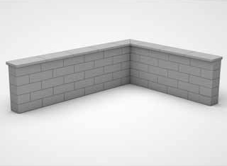
EXTERNAL CORNER
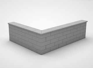
The 90° corner is formed by alternating the orientation of the blocks so that they are “interlocked” with one another.
COLUMN BLOCK
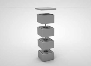
The individual column blocks are laid one on top of another. The seal profiles must be grouted on the column block beforehand. The hollow chambers (cavities) must then be reinforced and filled with mortar.
We use cookies to personalise content and to analyse our traffic. You consent to our cookies if you continue to use our website.
